
PTFE Slide Plates
These are used where supports with low coefficient of friction (0.1) are required by stress analysis calculations. They are used below Rest Supports like Trunions, Shoes as well as Springs.
Sometimes equipment also needs to slide on low friction support plates due to stress analysis requirements. Detail drawings may have to be prepared and provided to mechanical department.
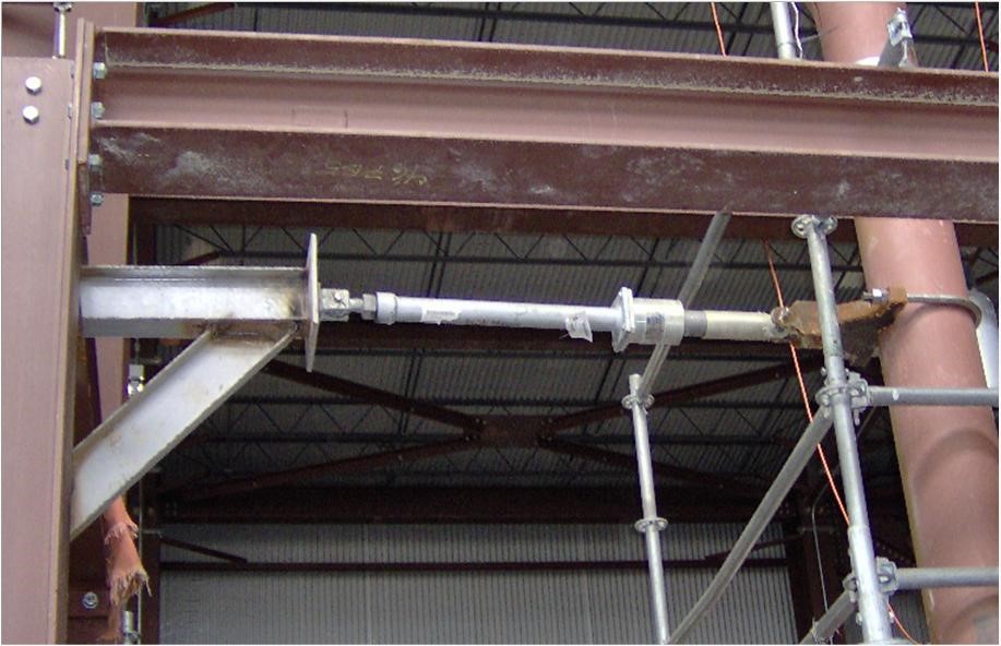
Hydraulic Shock Absorbers / Snubbers
Stress analysis may dictate need of hydraulic shock absorbers / Snubbers. Necessary details must be prepared for their procurement in time.
- Erection Length
- Travel range required to allow the free thermal expansion.
- The dynamic load to be contained.
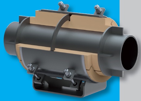
A mechanical snubber is a mechanical device designed to protect components from excess shock or sway caused by seismic disturbances or other transient forces. During normal operating conditions, the snubber allows for movement in tension and compression. When an impulse event occurs, the snubber becomes activated and acts as a restraint device. The device becomes rigid, absorbs the dynamic energy, and transfers it to the supporting structure.
Clamped Shoes
For piping where it is not advisable to execute erection welds at site, clamped shoes should be adopted. Generally these piping lines are the following.
- For a metallic piping when piping class dictates post welding heat treatment (PWHT) .
- Metallic piping with thin wall pipes. (CS < Sch. 20, SS < Sch 10S).
- Internally lined piping.
- Special Materials Piping such as Titanium, Hastelloy, Monel, Cupronickel.
- Hot Dipped Galvanized Piping.
- RTRP or PVC Piping.
- Pipelines with electric insulation.
[google-square-ad]
The clamped support is not necessary on metallic piping when the Piping Class requires PWHT according to ASME code, since the support welds do not require PWHT.
Spring Supports
Spring supports are specified if Stress Analysis of a piping system dictates their use. They must be designed as per stress analysis requirements by stress analysis specialist.
The characteristics of each spring support, such as operating load and the working travel shall comply with the stress analysis calculations. Data sheets shall be prepared for both variable load type spring supports and constant load type spring supports, for the purpose of support procurement.
When short delivery time is required, the data sheets can be prepared in two stages. First stage allows issue of purchase order which includes information required to identify type and quantity of spring supports. Second stage includes dimensions for construction of accessories such as tie rods, clevis, pins etc.
High Temperature Piping Supports
The supports for piping with fluid temperature >= 600 deg. C is normally of carbon steel clamped type. A layer of calcium silicate is placed between pipe and support clamp in order to thermally insulate the two elements.
These supports shall be defined and indicated in proper project documents like Standards, Specifications and drawings.
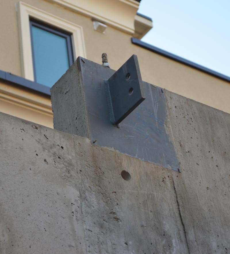
Pipe Supports from Concrete Structures.
Piping supports located on concrete structures are normally connected to concrete structure by means of metallic embedded plates or passing through holes for the insertion of connecting rods.
The location, sizing and loads of plates and tie rods should be provided to Civil Department in time.
When new supports are required after construction of concrete structure, it is possible to use clamps on columns or expansion bolts. However use of such methods must be minimised. Their feasibility in the project must be ascertained with Civil Department.
Supports for Cryogenic Piping
Supports for cryogenic piping normally consist of a load-bearing steel component and a high density-polyurethane component in contact with the pipe. This arrangement avoids formation of condensate or ice near each support. Also it avoids local brittleness of metallic supports under certain thermal conditions.
Supports for Cupro-Nickel Piping
Cupro-Nickel piping is generally supported with carbon steel clamped supports. A layer of neoprene or similar material is placed between support clamp and the pipe to prevent direct contact between pipe and support materials in order to avoid galvanic corrosion phenomenon.
For horizontal piping, the maximum allowable span between two rests is as shown below.
| NPS | Inch | 1/2 | 3/4 | 1 | 1 1/2 | 2 | 3 | 4 | 6 | 8 | 10 | 12 | 14 | 16 |
| Nominal Thickness | mm | 2. 11 | 2. 11 | 2. 77 | 2. 77 | 2. 77 | 3. 05 | 3. 05 | 3. 4 | 3. 76 | 4. 19 | 4. 57 | 4. 78 | 4. 78 |
| Max Span | L (m) | 2. 8 | 3. 1 | 3. 5 | 4. 1 | 4. 5 | 5. 1 | 5. 4 | 6. 1 | 6. 6 | 7. 1 | 7. 5 | 7. 8 | 7. 9 |
Notes :
- The spans indicated above are obtained in accordance with the ASME B31.3 code, on the basis of following assumptions.
- Continuous beam uniformly loaded
- Max allowable stress 25 MPa
- Beam maximum deflection 6 mm.
- Pipe weight calculated on the basis of nominal thickness.
- Calculation of moment of inertia and section modulus on the basis of nominal thickness.
- In case of concentrated loads on the pipes, like valves or supports for adjacent pipes, the max span indicated in the table should be verified on the basis of the above said concentrated loads.
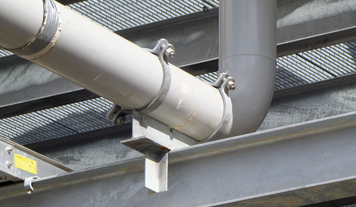
Supports for PVC Piping
Normally PVC Piping is continuously supported by means of a carbon steel L shape of same length as pipe. Corner of the L shape is oriented at the bottom. The pipe is bound to the steel member with I-bolts. Steel shape is located on the beams of pipe rack or dedicated structures. The supports for PVC piping will be defined and indicated in proper documents (standardization, specifications and drawings) issued for the project.
Supports for Resin Piping
The supports of resin pipes are normally of carbon steel clamped type. A layer of neoprene or similar material is placed between support clamp and pipe, in order to avoid local damage to pipe due to tightening of clamp.
The maximum allowable span between two rest supports of horizontal resin pipe is normally given by the pipe manufacturer on the basis of pipe mechanical characteristics. Example spacing chart is given below.
When metallic valves and/or heavy components are present in the piping, supports are required to prevent pipe bending. Provide
- Bolted type support on the metallic valve flange.
- Supports on resin pipe close to the valve.
| NPS | ID | Liquid with 21 Deg. C < t < 80 deg C | |||||||
| Pressure Class (bar) | |||||||||
| Inch | mm | L (m) | L (m) | L (m) | L (m) | L (m) | L (m) | L (m) | L (m) |
| 1 | 25 | (1) | (1) | (1) | (1) | (1) | (1) | (1) | 3.1 |
| 1 1/2 | 40 | (1) | (1) | (1) | (1) | (1) | (1) | (1) | 3.7 |
| 2 | 50 | (1) | (1) | (1) | (1) | (1) | (1) | 4 | 4.2 |
| 3 | 80 | (1) | (1) | (1) | (1) | (1) | 5.2 | 4.6 | 5.1 |
| 4 | 100 | (1) | (1) | (1) | (1) | 5.7 | 4.7 | 5.3 | 6 |
| 6 | 150 | (1) | (1) | (1) | 4.6 | 5.5 | 5.5 | 6.7 | 7.3 |
| 8 | 200 | (1) | (1) | 4.6 | 5.7 | 6.2 | 6.4 | 7.6 | 8.3 |
| 10 | 250 | (1) | 4.9 | 5.5 | 6.4 | 6.9 | 7.3 | 8.6 | 9.3 |
| 12 | 300 | (1) | 5.4 | 5.8 | 6.9 | 7.5 | 8 | 9.3 | 10.2 |
| 14 | 350 | 4.7 | 5.8 | 6.2 | 7.4 | 8.1 | 8.7 | 10.1 | (2) |
| 16 | 400 | 5 | 6.2 | 6.9 | 7.9 | 8.8 | 9.3 | (2) | (2) |
| 18 | 450 | 5.3 | 6.6 | 7.2 | 8.3 | 9.3 | (2) | (2) | (2) |
| 20 | 500 | 5.6 | 7.3 | 7.5 | 8.8 | 9.8 | (2) | (2) | (2) |
| 24 | 600 | 6.1 | 7.9 | 8.3 | 9.8 | 10.7 | (2) | (2) | (2) |
Note : Considered design pressure is 100% of the pressure class.
- Pressure class not available. to find the max allowable span it is necessary to make reference to the first available pressure class.
- Pressure class not available.
Temporary Pipe Supports
When temporary supports are necessary, their choice and management is carried out using the same modalities of permanent supports.
Temporary supports for piping are clamped type. Posts and portals are with bolted connections to facilitate dismantling and removal.
Following note is added on isometrics for temporary supports : Support to be removed before the declaration of plant mechanical completion.
Special Pipe Supports
Special supports are required due to stress analysis requirements when no standard support is available to satisfy stress requirements.
The drawing should include :
- Function description of the support along with identifying code as per project standard.
- In scale graphic drawing of support, complete with all components and dimensions necessary for construction and erection.
- Position and dimensions of field welds, if any.
- Material list for the prefabrication of components, as per project standard.
- When support is applicable to one line only, the line number shall be indicated on drawing along with position related to structure.