
Pipeline earth work includes ROU clearing, Grading, Trenching, Back-filling, Micro-tunnelling, Crossing etc.
Tags : #Piping_Engineering #Pipeline_Engineering #Pipeline_Trenching #Pipeline_Micro_tunneling #Pipeline_Earthwork.
INDEX
- Pipeline ROU Clearing and Grading
- Pipeline Trenching
- Pipeline Micro-Tunnelling
- Pipeline Crossing
- Pipeline Backfilling
- Pipeline Markup, Cleanup and Restoration
Pipeline ROU Clearing and Grading
In this activity, all obstacles causing hindrance in construction / laying pipeline are removed. Entire ROU is graded for movement of equipments and vehicles. Temporary approaches/bridges, if required, are constructed for movement of equipment vehicles and personnel.

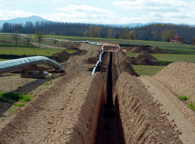
Pipeline Trenching
Onshore Pipelines
Onshore pipelines should be buried to protect them from mechanical damage, fires and tempering. The recommended minimum covers are given in ANSI/ASME B31.8 Article 841.142.
In determining depth cover in agricultural areas, the depth of ploughing and of drain systems shall be considered. A cover of 1 m shall be adequate in most cases. In grazing land, where fencing activities are common, a depth cover of 0.8 m is in general adequate.
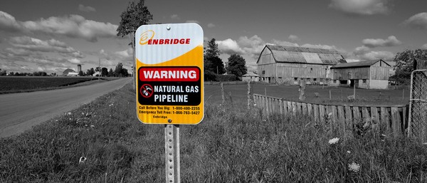
The location of buried pipelines shall be identified by markers. In areas where the risk of interference by mechanic excavators is high, a warning table should be installed in the excavation above the pipeline to further lower the risk.
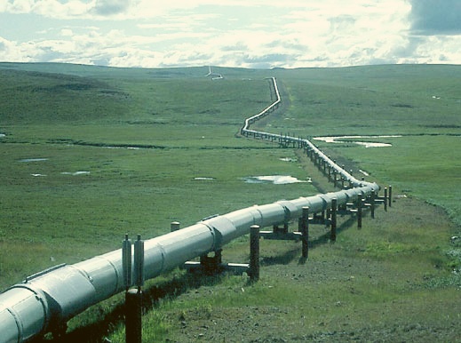
Any non-buried pipeline sections shall be justified on an individual basis, and shall be installed clear of the ground to avoid external corrosion. Pipe supports should be designed according to standard.
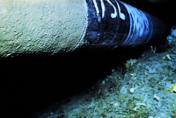
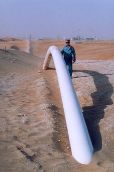
Offshore Pipelines
The section of pipeline within the shore approach should be buried to a depth to ensure that exposure due to erosion will not take place. There is otherwise no requirement to trench or bury offshore pipelines unless necessary in order to achieve pipeline stability, mechanical protection or thermal insulation.
It should be noted that protection against dragging anchors from large ships, particularly in soft soils, required significant or even impracticable burial depths.
Pipelines of 16” and above, with high impact resistant concrete coating, can generally withstand the impact of fishing gear (e.g. trawl boards) and therefore need not be trenched. However since several installed parameters may vary from case to case, this should be verified on individual basis.
When soil properties and the environment conditions are suitable, the pipeline may self-bury within an acceptable in period of time, removing the need for physical burial. The analysis of the self burial process is complex and often based on local records/observations; therefore specialized expertise should be sought.
Upheaval Buckling of High Temperature Pipelines
Buried pipelines operating at high temperatures may be susceptible to upheaval buckling caused by high compressive loads. Upheaval buckling can be prevented either by expansion offsets regularly spaced along the pipeline, or a sufficient burial cover. The use of expansion bellows to accommodate thermal movement is not recommended.
Recommended Minimum Cover for Onshore Pipelines
| Location | Minimum cover (m) in Normal ground (Note 1) | Minimum cover (m) in Rock, requiring blasting |
| Class 1Class 2Class 3 and 4 | 0.81.01.2 | 0.60.81.0 |
| Public roads and railways crossings | 1.5 | 1.2 |
NOTE 1: The cover refers to the undisturbed ground level.
Stability
- All submerged pipelines, e. offshore pipelines and sections of onshore pipelines in swamps, floodable areas, high water table areas, river crossings, etc., should be stable under the combined action of hydrostatic and hydrodynamic forces. The on-bottom stability can be achieved by increasing the pipe wall thickness, by the application of concrete weight coating, by spaced anchor points, by trenching, or by burial.
- Special considerations shall be given to pipelines installed in weak soils (e.g. peat), at dyke crossings, etc. where differential settlements may lead to pipeline loss of integrity.
- The one year return wave and steady state current conditions should be used for the analysis of stability during the installation phase. The one hundred year environmental return conditions should be used for the analysis during the operation phase. The negative buoyancy should be sufficient to prevent unacceptable lateral pipeline displacements.
General Notes :
- Trench excavation is carried out along staked centreline of pipeline.
- The width of excavation for trench shall be minimum (pipe diameter plus 200 mm on either side).
- Depth of trench shall be specified (Normal – 1 Meter, Road : 1.2 M, River 1.5 M, Railway : 1.7 M etc)
- In case of trenching in rocky areas, blasting is performed with the guidelines and safety rules of chief control of explosives, Nagpur.
- In case where rock/gravel or murrum/hard soil is encountered in the bottom of trench, padding material (minimum compacted thickness of 150 mm) shall be provided.
- When up-floating of the pipe line after backfilling is anticipated, antibuoyancy measures are provided in such areas e.g. weighing by applying continuous concrete, installing saddle weights etc.
Youtube Videos
Pipeline Equipment – Trenching Wheel In Action :
How to dig pipeline ditch :
Caterpillar CAT 345D L digging a trench for a gas pipeline :
CTC Marine RT-1 Rock Trencher Animation :
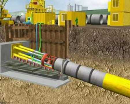
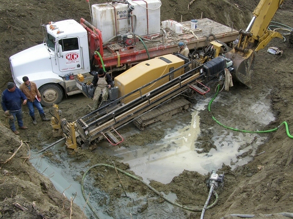
Pipeline Micro-Tunnelling
Micro Tunneling process uses a Micro Tunnel Boring Machine (MTBM) combined with pipe jacking technique. Pipe jacking from launch shaft to reception shaft. Hydraulic Jacks are used to push Jacking pipes behind a tunnel boring machine. A carrier pipe is inserted in jacking pipe.
Advantages
- Micro-tunnelling can be used wherever HDD cannot be done.
- Crossing of Rivers with gravels, cobbles & boulders.
- Installation of more than one pipe in the tunnel.
- Precise installation and Minimum space at both ends.
- Can be done in curved path also.
Youtube Videos
Microtunnelling :
Pipeline Crossing
Onshore Pipelines
The use of casings for the crossing of roads or railways should be discouraged because of the difficulty in providing the pipeline with adequate protection against external corrosion. When casings are stipulated by local authorities, the cathodic protection of the pipeline section within the casing shall be carefully reviewed.

Recommendations on pipeline crossings of roads and railways are contained in API RP 1102.
Directional drilling is particularly suitable for long crossings e.g. rivers and waterways; the method can achieve large burial depths and at is insensitive to current, river traffic etc. The recommended minimum covers at the crossings is given in Table above.
A minimum vertical separation of 0.3 m should be kept between the pipeline and any other buried structures e.g. existing pipelines, cables and foundations etc.
Offshore Pipelines
A minimum vertical separation of 0.3 m should be kept between the pipeline and any other underwater structures such as existing pipelines and submarine cables. Mats or equivalent means should be used for local positive separation at crossing locations.
Methods Used
- Cased and Un-Cased crossings for Roads and Railways.
- Open cut and horizontal directional drilling (HDD) for minor and major river crossing.
- Jacking and boring
- Micro-Tunneling
Youtube Videos
Mud Creek Pipeline Crossing :
Horizontal Directional Drilling, The Next Generation (HDD) :
River Crossing using HDD :
Horizontal Directional Drilling – how it works :
Pipeline Backfilling
Backfilling shall be carried out immediately after pipeline lowering in trench after inspection, so as to provide a natural anchorage for the pipeline, thus avoiding long exposure of coating to high temperature, damaging action of adverse weather conditions, sliding down of trench sides and pipeline movement in the trench.
Backfill material shall not contain any extraneous material or hard lumps of soil which can damage pipeline or coating or leave the voids in backfilled trench. After placing of initial backfill, proper compaction shall be done.

The surplus material shall be crowned (300 mm) directly over trench and adjacent excavated area on both side of trench. If trench are excavated in steep area where the slope is more than 10%, slope breakers shall be installed to prevent erosion of backfill. Stabilization of backfill shall be done in sandy area to have consolidated cover over the pipeline.
Youtube Videos
Backfilling Pipeline :
Back Fill :
Pipeline backfilling Finland :
Pipeline ROU Markup
Following type of markers shall be fabricated and installed along the pipeline route such that they do not cause any hindrance to the regular land user or traffic.
- Aerial Markers: At every 5 Kms.
- Kilometer Markers: At every 1 Km. & as per Alignment sheet
- Pipeline Warning Markers: At Road / Railway / River Crossings & Stations / Terminals
- ROU Boundary Markers: At every 750 Mtrs. & as per Alignment sheet
- Direction Markers: At significant turning points
- Navigational Markers: At bank of Navigational Course
- OFC Markers: At OFC Joints
Pipeline ROU Cleanup and Restoration
ROU and all sites used for construction of pipeline , water crossing and other structures shall be restored as per satisfaction of authority having jurisdiction over it.
- Damages to roads, bridges, fences etc. damaged during construction shall be restored to original.
- The bed of water course shall be restore to the original level.
- The banks and any excavated area shall be restored to original levels .
- The banks shall also be stabilized.
- On completion of clean-up, the ROU shall be restored to such stable and usable condition as may be reasonably consistent with the condition of the ROU prior to laying the pipeline.
- The release note from the land owners regarding satisfactory indemnification and restoration of land shall be obtained from land owner.