It is very easy to recognize Welding Neck Flanges as they have long tapered hub, with thickness of hub gradually reducing to match that of connected pipe or fitting.

This long tapered hub provides an important reinforcement for use in several applications involving high pressure, sub-zero and / or elevated temperatures. The smooth transition from flange thickness to pipe or fitting wall thickness effected by the taper is extremely beneficial, under conditions of repeated bending, caused by line expansion or other variable forces.
Welding
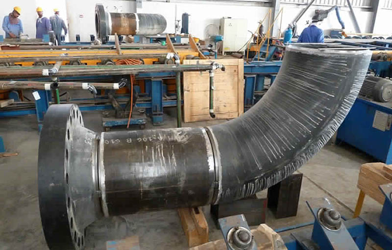
These flanges are bored to match the inside diameter of the mating pipe or fitting so there will be no restriction of product flow. This prevents turbulence at the joint and reduces erosion. They also provide excellent stress distribution through the tapered hub.
This flange type will be welded to a pipe or fitting with a single full penetration, V weld (Buttweld).
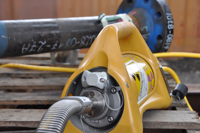
Radiography
It is comperatively easy to radiograph butt welds. As weld neck flanges are buttwelded to connected pipe, these flanges are regulary used in critical services such as high temperature and pressure piping, where radiography is required as per applicable design code.
Applications
This type of flange has been used successfully at pressures up to 5,000 psi.
Their thick and strong structure makes these flanges expensive and are used mostly in high temperature, flammable and toxic services.
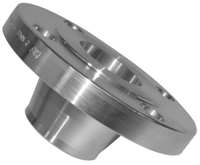
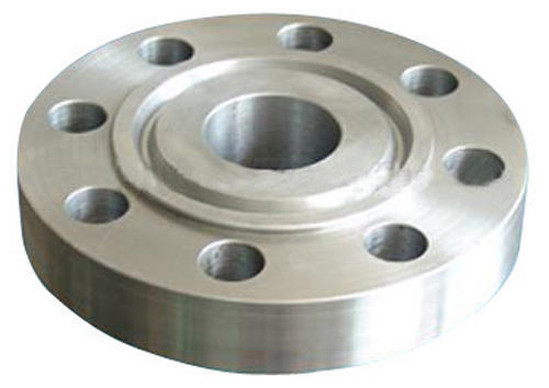
Flange Facings
Most commonly used facings for Weld Neck Flanges are Raised Face and Ring Type Joint.
Dimensional Standards
Most commonly used dimensional standards for Weld Neck Flanges are :
ASME B16.5 : Pipe Flanges and Flanged Fittings
This standard provides dimensions for weld neck flanges for size range 1/2″ to 24″ and for ratings 150#, 300#, 400#, 600#, 900#, 1500# and 2500#.
Classes 150 and 300 pipe flanges and companion flanges of fittings are regularly furnished with 2 mm (0.06 in.) raised face, which is in addition to the minimum flange thickness, tf. Classes 400, 600, 900, 1500, and 2500 pipe flanges and companion flanges of fittings are regularly furnished with 7 mm (0.25 in.) raised face, which is in addition to the minimum flange thickness, tf.
- 150#, 300#, 400#, 600#, 900# and 1500# : 1/2″ to 24″
- 2500# : 1/2″ to 12″
ASME B16.47 : Large Diameter Steel Flanges
This standards provides dimensions only for Weld Neck Flanges and Blind Flanges for size range 26″ to 60″. Rating class designations provided are : 75, 150, 300, 400, 600 and 900. Series A specifies flange dimensions for general
use flanges. Series B specifies flange dimensions for compact flanges that, in most cases, have smaller bolt circle diameters than Series A flanges. These two series of flanges are, in general, not interchangeable.
Compact Series B Flanges are used for congested spaces such as revamp work or marine applications.
Classes 75, 150, and 300 flanges are regularly furnished with a 2 mm (0.06 in.) raised face. Classes 400, 600, and 900 flanges are regularly furnished with a 7 mm (0.25 in.) raised face.
- Series A : 150# , 300#, 400# and 400# : 26″ to 60″
- Series A : 900# Series A from 26″ to 48″.
- Series B : 75#, 150# and 300# from 26″ to 60″.
- Series B : 400#, 600# and 900# from 26″ to 36″
MSS-SP-44 : Steel Pipeline Flanges
While these flanges are designated by the customary ANSI Standard Class 150, 300, 400, 600, and 900, their use is almost entirely confined to cross country transmission pipelines at atmospheric temperatures. The flanges have been designed primarily for use at their cold ratings which conform to the ANSI Standard B16.5 ratings of 100 deg.F. and are intended primarily for attachment to relatively thin-wall, high-strength cold worked pipe, and high-strength butt-welding fittings in pipeline service at temperatures of 450 deg.F and lower.
DIN EN 1092/1 Type 11 Weld Neck Flanges
This european standard for flanges contains pressure ratings of : PN10, PN16, PN25, PN40, PN63, PN100, PN160, PN250, PN320 and PN400.
- PN 10 : Size Range DN 10 to DN 3000.
- PN 16: Size Range DN 10 to DN 2000.
- PN 25: Size Range DN 10 to DN 2000.
- PN 40: Size Range DN 10 to DN 600.
- PN 63: Size Range DN 10 to DN 1200.
- PN 100: Size Range DN 10 to DN 500.
- PN 160: Size Range DN 10 to DN 300.
- PN 250: Size Range DN 10 to DN 250.
- PN 320: Size Range DN 10 to DN 250.
- PN 400: Size Range DN 10 to DN 200.
Piping Material Specification
Piping Material Specification for Weld Neck Flanges include following details :
- Nominal Pipe Size of Flange.
- Flange Rating.
- Thickness of welding end of this flange as it should be same
as connecting pipe. - Applicable dimensional standard such as ASME B16.5.
- Material of Construction Such as A105 and A181 for Carbon
steel, A182 for Stainless Steel, A350 for Low Temperature services.