
Blinds, Spacers and Spectacle Blinds are used for the purpose of positive shut off of a piping system where mere shut off using valves is not sufficient as valves are prone to leakage. These are generally used in hazardous services like hydrocarbon fluids.
This page provides metric dimensions of Female Ring Joint Line Blanks as per ASME B16.48
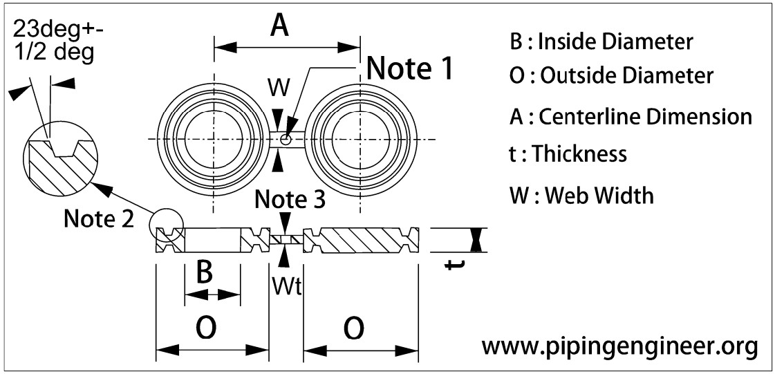
Available dimensions are : A : Distance between Centerlines | B : Inside Diameter | O : Outside Diameter | t : Thickness of Blank | W : Web Width | Wt : Web Thickness : Note 2
150# FRJ Line Blanks
| NPS | B Inside Diameter | O Outside Diameter | A Center to Center | t Blank Thickness | W Web Width |
|---|---|---|---|---|---|
| 1 | 34 | 64 | 80 | 19.1 | 51 |
| 1-1/4 | 42 | 73 | 90 | 19.1 | 51 |
| 1-1/2 | 48 | 83 | 100 | 19.1 | 57 |
| 2 | 61 | 102 | 120 | 19.1 | 57 |
| 2-1/2 | 73 | 121 | 140 | 22.4 | 57 |
| 3 | 89 | 133 | 150 | 22.4 | 57 |
| 3-1/2 | 102 | 154 | 175 | 22.4 | 64 |
| 4 | 114 | 172 | 190 | 22.4 | 64 |
| 5 | 141 | 194 | 215 | 25.4 | 70 |
| 6 | 168 | 219 | 240 | 25.4 | 83 |
| 8 | 219 | 273 | 300 | 28.4 | 95 |
| 10 | 273 | 330 | 360 | 31.8 | 102 |
| 12 | 324 | 406 | 430 | 35.1 | 121 |
| 14 | 356 | 426 | 475 | 35.1 | 127 |
| 16 | 406 | 483 | 540 | 38.1 | 127 |
| 18 | 457 | 546 | 580 | 41.1 | 127 |
| 20 | 508 | 597 | 635 | 41.1 | 127 |
| 24 | 610 | 711 | 750 | 47.8 | 152 |
300# FRJ Line Blanks
| NPS | B Inside Diameter | O Outside Diameter | A Center to Center | t Blank Thickness | W Web Width |
|---|---|---|---|---|---|
| 1/2 | 21 | 51 | 65 | 15.7 | 38 |
| 3/4 | 27 | 64 | 80 | 19.1 | 45 |
| 1 | 34 | 70 | 90 | 19.1 | 51 |
| 1-1/4 | 42 | 79 | 100 | 22.4 | 51 |
| 1-1/2 | 48 | 90 | 115 | 22.4 | 57 |
| 2 | 61 | 108 | 125 | 25.4 | 57 |
| 2-1/2 | 73 | 127 | 150 | 28.4 | 57 |
| 3 | 89 | 146 | 170 | 28.4 | 57 |
| 3-1/2 | 102 | 159 | 185 | 28.4 | 64 |
| 4 | 114 | 175 | 200 | 31.8 | 64 |
| 5 | 141 | 210 | 235 | 35.1 | 70 |
| 6 | 168 | 241 | 270 | 35.1 | 83 |
| 8 | 219 | 302 | 330 | 41.1 | 95 |
| 10 | 273 | 356 | 385 | 44.5 | 102 |
| 12 | 324 | 413 | 450 | 50.8 | 121 |
| 14 | 356 | 457 | 515 | 53.8 | 127 |
| 16 | 406 | 508 | 570 | 57.2 | 127 |
| 18 | 457 | 575 | 630 | 60.5 | 127 |
| 20 | 508 | 635 | 685 | 69.9 | 127 |
| 24 | 610 | 749 | 810 | 79.2 | 152 |
400# FRJ Line Blanks
| NPS | B Inside Diameter | O Outside Diameter | A Center to Center | t Blank Thickness | W Web Width |
|---|
600# FRJ Line Blanks
| NPS | B Inside Diameter | O Outside Diameter | A Center to Center | t Blank Thickness | W Web Width |
|---|---|---|---|---|---|
| 1/2 | 21 | 51 | 65 | 19.1 | 38 |
| 3/4 | 27 | 64 | 80 | 22.4 | 45 |
| 1 | 34 | 70 | 90 | 22.4 | 51 |
| 1-1/4 | 42 | 79 | 100 | 22.4 | 51 |
| 1-1/2 | 48 | 90 | 115 | 22.4 | 57 |
| 2 | 61 | 108 | 125 | 28.4 | 57 |
| 2-1/2 | 73 | 127 | 150 | 31.8 | 57 |
| 3 | 89 | 146 | 170 | 31.8 | 57 |
| 3-1/2 | 102 | 159 | 185 | 35.1 | 64 |
| 4 | 114 | 175 | 215 | 35.1 | 64 |
| 5 | 141 | 210 | 265 | 38.1 | 70 |
| 6 | 168 | 241 | 290 | 44.5 | 83 |
| 8 | 219 | 302 | 350 | 50.8 | 95 |
| 10 | 273 | 356 | 430 | 57.2 | 102 |
| 12 | 324 | 413 | 490 | 63.5 | 121 |
| 14 | 356 | 457 | 525 | 66.5 | 127 |
| 16 | 406 | 508 | 605 | 73.2 | 127 |
| 18 | 457 | 575 | 655 | 79.2 | 127 |
| 20 | 508 | 635 | 725 | 88.9 | 127 |
| 24 | 610 | 749 | 840 | 104.6 | 152 |
900# FRJ Line Blanks
| NPS | B Inside Diameter | O Outside Diameter | A Center to Center | t Blank Thickness | W Web Width |
|---|---|---|---|---|---|
| 1/2 | 21 | 61 | 80 | 22.4 | 38 |
| 3/4 | 27 | 67 | 90 | 22.4 | 45 |
| 1 | 34 | 71 | 100 | 22.4 | 51 |
| 1-1/4 | 42 | 81 | 110 | 25.4 | 51 |
| 1-1/2 | 48 | 92 | 125 | 25.4 | 64 |
| 2 | 61 | 124 | 165 | 31.8 | 51 |
| 2-1/2 | 73 | 137 | 190 | 35.1 | 67 |
| 3 | 89 | 155 | 190 | 35.1 | 67 |
| 4 | 114 | 181 | 235 | 41.1 | 73 |
| 5 | 141 | 216 | 280 | 44.5 | 73 |
| 6 | 168 | 241 | 315 | 47.8 | 73 |
| 8 | 219 | 308 | 395 | 57.2 | 80 |
| 10 | 273 | 362 | 470 | 63.5 | 121 |
| 12 | 324 | 419 | 535 | 73.2 | 121 |
| 14 | 356 | 467 | 560 | 82.6 | 121 |
| 16 | 406 | 524 | 615 | 91.9 | 127 |
| 18 | 457 | 594 | 685 | 101.6 | 133 |
| 20 | 508 | 648 | 750 | 111.3 | 127 |
| 24 | 610 | 772 | 900 | 133.4 | 140 |
1500# FRJ Line Blanks
| NPS | B Inside Diameter | O Outside Diameter | A Center to Center | t Blank Thickness | W Web Width |
|---|---|---|---|---|---|
| 1/2 | 21 | 61 | 80 | 22.4 | 38 |
| 3/4 | 27 | 67 | 90 | 25.4 | 45 |
| 1 | 34 | 71 | 100 | 25.4 | 54 |
| 1-1/4 | 42 | 81 | 110 | 25.4 | 54 |
| 1-1/2 | 48 | 92 | 125 | 28.4 | 57 |
| 2 | 61 | 124 | 165 | 35.1 | 54 |
| 2-1/2 | 73 | 137 | 190 | 38.1 | 57 |
| 3 | 89 | 168 | 205 | 44.5 | 73 |
| 4 | 114 | 194 | 240 | 47.8 | 76 |
| 5 | 141 | 229 | 290 | 53.8 | 76 |
| 6 | 168 | 248 | 315 | 60.5 | 79 |
| 8 | 219 | 318 | 395 | 73.2 | 86 |
| 10 | 273 | 371 | 480 | 82.5 | 133 |
| 12 | 324 | 438 | 570 | 101.6 | 133 |
| 14 | 356 | 489 | 635 | 111.3 | 140 |
| 16 | 406 | 546 | 705 | 124 | 146 |
| 18 | 457 | 613 | 775 | 133 | 152 |
| 20 | 508 | 673 | 830 | 142.7 | 165 |
| 24 | 610 | 794 | 990 | 168.1 | 178 |
2500# FRJ Line Blanks
| NPS | B Inside Diameter | O Outside Diameter | A Center to Center | t Blank Thickness | W Web Width |
|---|---|---|---|---|---|
| 1/2 | 21 | 65 | 90 | 25.4 | 38 |
| 3/4 | 27 | 73 | 95 | 28.4 | 45 |
| 1 | 34 | 83 | 110 | 28.4 | 54 |
| 1-1/4 | 42 | 102 | 130 | 35.1 | 54 |
| 1-1/2 | 48 | 114 | 145 | 38.1 | 61 |
| 2 | 61 | 133 | 170 | 41.1 | 57 |
| 2-1/2 | 73 | 149 | 195 | 47.8 | 61 |
| 3 | 89 | 168 | 230 | 50.8 | 76 |
| 4 | 114 | 203 | 270 | 63.5 | 83 |
| 5 | 141 | 241 | 325 | 73.2 | 89 |
| 6 | 168 | 279 | 370 | 82.6 | 95 |
| 8 | 219 | 340 | 440 | 98.6 | 95 |
| 10 | 273 | 425 | 540 | 117.3 | 91 |
| 12 | 324 | 495 | 620 | 133.4 | 152 |
| NPS | B Inside Diameter | O Outside Diameter | A Center to Center | t Blank Thickness | W Web Width |
Source of Data
Dimensions of Line Blanks are as per ASME B16.48 : Line Blanks
Dimension Terms
- A : Distance between Centerlines
- B : Inside Diameter
- O : Outside Diameter
- t : Thickness of Blank
- W : Web Width
- Wt : Web Thickness : Note 2
GENERAL NOTE
(a). All dimensions are in millimeters.
NOTES
(1). Hole Size (where required due to bolt spacing) shall be the same as the flange bolt hole and located such that it will not interfere with bolting between two flanges.
(2). The thickness of the web (or tie bar) dimension, Wt shall be as determined by para.3.1 of ASME B16.48.
(3). Female ring-joint groove dimension shall be in accordance with ASME B16.5
(4). Oval ring-joint dimensions shall be in accordance with ASME B16.20, except Th = T + t where T is the ring height specified in ASME B16.20
General Notes
All Dimensions are in millimeters.
Notes
(1) Hole size (where required due to bolt spacing) shall be the same as the flange bolt hole and located such that it will not interfere with bolting between two flanges.
(2) Female ring-joint groove dimensions shall be in accordance with ASME B16.5.
(3) The thickness of the web (or tie bar) dimension, Wt, shall be as determined by para. 3.1. of ASME B16.48