Introduction
The selection of the route for a pipeline shall take full account of the associated risks, particularly safety and environmental risks, the accessibility for maintenance and inspection, as well as normal direct cost considerations.
Surveys
Detailed survey data should be available prior to finalising the pipeline route and carrying out detailed design. These data include:
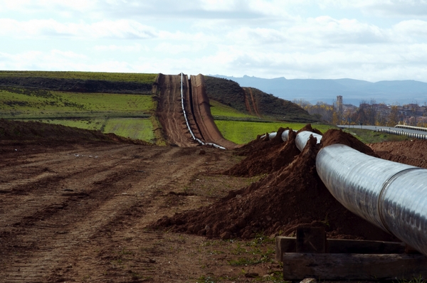
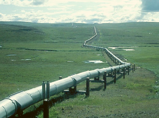
ONSHORE PIPELINES
- Population and building densities for the establishment of location classes, location of inhabited buildings, taking into account any future land development plans.
- Topographical data, location of rivers, roads and railways, including type and density of traffic.
- Records of any existing special features which will need reinstatement after construction is completed.
- Soil investigation for foundation design (burial and/or supports design), subsidence areas (e.g. due to mining activities).
- Soil resistivity for cathodic protection design.
- Environmental data (climatic, floods, earthquake, landslides, current at river crossings, vegetation, fauna).
- Cadastral : Land ownership map including type of land
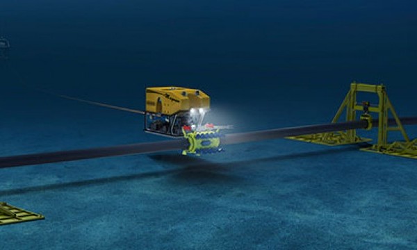
Offshore Pipeline
- Seabed topographical data, location of rock/coral outcrops.
- Soil investigation for foundation and on-bottom stability design.
- Fishing, shipping and other sea users activity data.
- Environmental data (Climatic, currents, waves, bathymetry, earthquakes, landslides).
- Third party facilities and concession areas.
Establishment of location classes for onshore pipelines
- Based on the survey data, appropriate location classes shall be identified along the pipeline route for pipelines transporting category C and D fluids, in accordance with ANSI/ASME B31.8 Article 840.2.
- There is no specific requirement for pipelines transporting category A and B fluids, apart from access requirements during construction and for maintenance and emergency services during operations.
- ANSI/ASME B31.8 identifies 4 location classes, ranging from location class 1 (sparsely populated areas) to location class 4 (densely populated areas).
- Since location classes are used for the determination the design factor (3.4.1), the route selection shall take due regard for the cost impact on pipeline sections in location classes of higher category (e.g. class 3 and class 4).
Proximity to occupied buildings (onshore pipelines)
- Compared to pipelines transporting category A and B fluids, pipelines transporting category C and D fluids constitute potentially higher hazards to people
- There are no provisions in ANSI/ASME B31.4/8 to cover this, apart from the location classes defined in which only address population
- For the purpose of initial routing, Appendix 1 provides guidance for establishing minimum distances of pipelines from occupied buildings depending on the type of the fluid, the pipeline diameter and its maximum operating pressure.
- Final routing should be established following the pipeline safety assessment.
Proximity to other facilities
- For fluid categories B, C and D, the separation requirements between the pipeline (including pig traps) and other facilities within the plant fences or on the offshore platform should be in accordance with Company Specification.
- For the definition of area classifications around the pipeline, refer to the Institute of Petroleum Model Code of Safe Practice Part 15.
Special routing considerations
- In the derivation of the route, due consideration shall be given to the anticipated installation technique.
- This is particularly relevant to offshore pipelines.
ONSHORE PIPELINES
- All pipelines shall have a permanent right of way with a width ranging from 4 m for DN150 and below, to 10 m for DN600 and above.
- The pipeline route should be centered on the right of way.
- The radius of curvature of the pipeline foundation along route should not be less than 500xD, D being the pipeline diameter.
- Hot bends or field bends should be used when lower values are necessary.
- When several pipelines are installed in the same trench, the separation between 2 adjacent pipelines shall be 0.3 m minimm.
- The minimum distance for pipelines installed in a separate trench alongside existing buried pipeline should range from 2 m for DN 150 and below to 5 m for DN 900 and above.
- The crossing of existing pipelines, cables, power lines, roads, railways and waterways should be at an angle between 60 and 90 degrees.
- When installing a pipeline along power lines, the horizontal distance from any of the power cables and posts should be at least 10 m for power lines at 110 kv and above and 4 m for power lines below 110 kv.
Offshore Pipelines
- The radius of curvature of the pipeline along route should not be less than 2000xD, D being the pipeline
- When lower values are necessary, a detailed analysis of the pipeline lateral stability during laying should be carried out.
- Pipelines close to offshore platforms should as far as possible, be arranged in corridors to facilitate the anchoring of vessels for support and future construction activities at the platform.
- Straight lengths of pipe are normally necessary for start-up.
- Risers should be protected from the marine activity around the platform and except for category A fluids, located away from the living quarters.
- The crossing of existing pipelines and submarine cables should be at right angles.
- When this imposes excessive additional route length, lower crossing angles may be used but not lower than 30 degrees.
- The distance between parallel pipelines should not be less than 10 meters or the value compatible with the installation equipment whichever is higher.
Installation of Bench Marks, Turning Points.
- Stake marker in center line of pipeline at a distance of max 100m for centre line and for horizontal bends 10m and reference point from same.
- Stake two ROU markers at least at every 100m, painted in red and numbers in white in direction of flow.
- Chainage markers at every 250 m.