DIN flanges are industrial pipe flanges manufactured according to the standards set by the Deutsches Institut für Normung (the German Institute for standardization). They are primarily used in metric-based piping systems across Europe and global markets for fluid and gas transport.
DIN flanges are rated using the Pressure Nominale (PN) system. Common pressure classes include PN6, PN10, PN16, PN25, and PN40 (representing pressure in bar). This page provides dimensions for PN40 Weld Neck Flanges.
PN10 | PN16 | PN25 | PN40 | PN63 | PN100 | PN160 | PN250 | PN320 | PN400
| DN | D | k | d4 | S | d1 | d3 | d2 | f | b | h1 | h2 | r |
|---|---|---|---|---|---|---|---|---|---|---|---|---|
| 10 | 90 | 60 | 40 | 2.0 | 17.2 | 28 | 14 | 2 | 16 | 35 | 6 | 4 |
| 15 | 95 | 65 | 45 | 2.0 | 21.3 | 32 | 14 | 2 | 16 | 38 | 6 | 4 |
| 20 | 105 | 75 | 58 | 2.3 | 26.9 | 40 | 14 | 2 | 18 | 40 | 6 | 4 |
| 25 | 115 | 85 | 68 | 2.6 | 33.7 | 46 | 14 | 2 | 18 | 40 | 6 | 4 |
| 32 | 140 | 100 | 78 | 2.6 | 42.4 | 56 | 18 | 2 | 18 | 42 | 6 | 6 |
| 40 | 150 | 110 | 88 | 2.6 | 48.3 | 64 | 18 | 3 | 18 | 45 | 7 | 6 |
| 50 | 165 | 125 | 102 | 2.9 | 60.3 | 75 | 18 | 3 | 20 | 48 | 8 | 6 |
| 65 | 185 | 145 | 122 | 2.9 | 76.1 | 90 | 18 | 3 | 22 | 52 | 10 | 6 |
| 80 | 200 | 160 | 138 | 3.2 | 88.9 | 105 | 18 | 3 | 24 | 58 | 12 | 8 |
| 100 | 235 | 190 | 162 | 3.6 | 114.3 | 134 | 22 | 3 | 24 | 65 | 12 | 8 |
| 125 | 270 | 220 | 188 | 4.0 | 139.7 | 162 | 26 | 3 | 26 | 68 | 12 | 8 |
| 150 | 300 | 250 | 218 | 4.5 | 168.3 | 192 | 26 | 3 | 28 | 75 | 12 | 10 |
| 200 | 375 | 320 | 285 | 6.3 | 219.1 | 244 | 30 | 3 | 34 | 88 | 16 | 10 |
| 250 | 450 | 385 | 345 | 7.1 | 273.0 | 306 | 33 | 3 | 38 | 105 | 18 | 12 |
| 300 | 515 | 450 | 410 | 8.0 | 323.9 | 362 | 33 | 4 | 42 | 115 | 18 | 12 |
| 350 | 580 | 510 | 465 | 8.8 | 355.6 | 408 | 36 | 4 | 46 | 125 | 20 | 12 |
| 400 | 660 | 585 | 535 | 11.0 | 406.4 | 462 | 39 | 4 | 50 | 135 | 20 | 12 |
| 450 | 685 | 610 | 560 | 12.5 | 457.0 | 500 | 39 | 4 | 57 | 135 | 20 | 12 |
| 500 | 755 | 670 | 615 | 14.2 | 508.0 | 562 | 42 | 4 | 57 | 140 | 20 | 12 |
| 600 | 890 | 795 | 735 | 16.0 | 610.0 | 666 | 48 | 5 | 72 | 150 | 20 | 12 |
PN10 | PN16 | PN25 | PN40 | PN63 | PN100 | PN160 | PN250 | PN320 | PN400
Flange Bolting Details
PN10 | PN16 | PN25 | PN40 | PN63 | PN100 | PN160 | PN250 | PN320 | PN400
| DN | No | Dia.Hex | Length Hex | Dia.Stud | Length Stud |
|---|---|---|---|---|---|
| 10 | 4 | M12 | 50 | 1/2″ | 65 |
| 15 | 4 | M12 | 50 | 1/2″ | 65 |
| 20 | 4 | M12 | 55 | 1/2″ | 70 |
| 25 | 4 | M12 | 55 | 1/2″ | 70 |
| 32 | 4 | M16 | 60 | 5/8″ | 80 |
| 40 | 4 | M16 | 60 | 5/8″ | 80 |
| 50 | 4 | M16 | 65 | 5/8″ | 80 |
| 65 | 8 | M16 | 65 | 5/8″ | 85 |
| 80 | 8 | M16 | 70 | 5/8″ | 90 |
| 100 | 8 | M20 | 75 | 3/4″ | 95 |
| 125 | 8 | M24 | 85 | 7/8″ | 110 |
| 150 | 8 | M24 | 90 | 7/8″ | 115 |
| 200 | 12 | M27 | 105 | 1″ | 130 |
| 250 | 12 | M30 | 115 | 1-1/8″ | 145 |
| 300 | 16 | M30 | 125 | 1-1/8″ | 155 |
| 350 | 16 | M33 | 135 | 1-1/4″ | 170 |
| 400 | 16 | M36 | 145 | 1-3/8″ | 185 |
| 450 | 20 | M36 | 160 | 1-3/8″ | 200 |
| 500 | 20 | M39 | 165 | 1-1/2″ | 205 |
| 600 | 20 | M45 | 200 | 1-3/4″ | 250 |
PN10 | PN16 | PN25 | PN40 | PN63 | PN100 | PN160 | PN250 | PN320 | PN400
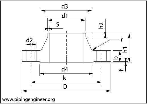
Legend
- D = Outside Diameter
- k = Diameter of Bolt Circle
- d2 = Diameter of Bolt Holes
- d4 = Diameter of Raised Face
- f = Height of Raised Face
- d1 = Outside Diameter of Neck
- b = Flange thickness
- h1 = Length of Flange
- h2 = Length of right end
- d3 = Neck Diameter
- r = Radius of Corners
- S = Wall thickness
- No. = Number of Bolts
- Dia.Hex = Diameter of Hex Bolts.
- Length Hex = Length of Hex Bolts.
- Dia.Stud = Diameter of Stud Bolts.
- Length Stud = Length of Stud Bolts.
General notes:
- Dimensions are in millimeters unless otherwise indicated.
- Butt-weld ends (must be specified when ordering) acc. to DIN 3239-1-R6 edge form 22 to DIN 2559 (DIN EN ISO 9692)
Extra notes:
- Hex bolt lengths and diameters & lengths of Stud Bolts are calculated.
- All bolt lengths calculated without washers, spring washers etc. and free threads (equals 1/3 time bolt diameter).
- Gasket thickness considered 3 mm for bolt length calculations.
- The dimensions of the bolts are for the type 11 weld neck flange.
- Please not that other types of flanges can be have different bolt hole diameters and thicknesses, so that the bolts even can have different dimensions.
PN10 | PN16 | PN25 | PN40 | PN63 | PN100 | PN160 | PN250 | PN320 | PN400