Introduction to Pumps
Various of pumps are used in chemical and petrochemical plants and refineries. Most widely used being the centrifugal pumps.
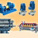 | This article lists out various types of Pumps used in a refinery and a chemical …Read More.. |
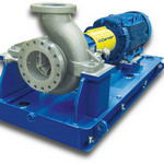
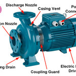 | Centrifugal pumps are the most widely used pumps in a chemical industry and refineries. They …Read More.. |
 | This article explains most common terms that the plant layout designer encounters when creating a pump …Read More.. |
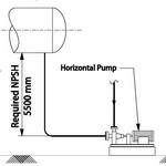 | NPSH can be defined as two parts: NPSH Available (NPSHA): The absolute pressure at the suction …Read More.. |
Pumps Equipment Layout
Pumps shall be located close to equipment from which they take suction. Pumps in a process unit shall not be located under pipeways.
Pumps Piping Layout
Maintenance
Piping shall be designed and arranged so that clearance is provided for removal of pumps and for drivers, also on end suction pumps so suction cover and pump impeller may be removed while the suction and discharge valves are in place.
Suction Lines
Suction lines shall be arranged in such a manner as to minimize offsets. Suction lines shall be short and as direct as possible. Suction lines shall step down from the equipment to the pump. Suction lines routed on sleeperways may rise to pump. Pump suction piping shall have the same pressure rating as the discharge piping up to and including the first suction block valve unless otherwise approved by the responsible engineer. Pump suction piping shall be arranged with particular care to avoid unnecessary pressure drop and vapour pockets. Reduction in size for front suction pumps shall be made as close to the pump as possible with a top flat reducer. For end suction pumps elbows shall not be directly connected to the suction flange. A straight piece minimum 3 times the line size shall be provided at the suction nozzle. For top suction, pump elbow shall not be directly connected to suction flange. A straight piece of minimum 5 times the nozzle size shall have to be provided at the suction nozzle.
Valve Operators
Valve handwheels shall be oriented, whenever possible, to be contained within the perimeter of the pump, but so that they shall not interfere with pump maintenance or motor removal. Valve handwheels shall be readily operable from grade.
Suction Strainers
Conical (witches hat) type temporary strainers shall be provided at all pump suctions and turbine inlets unless permanent strainers are required. Strainers are to be located before any reduction in pipe size. Strainers should have 200% of pipe cross-sectional area where possible. All strainers must be easily removable. Unless otherwise specified, T-type strainers shall be used on pump suction piping for sizes 2″ and above. Y-type strainers shall be used for all sizes in steam services and for pump suction lines below 2”.
Discharge Check Valves
Check valves shall be installed at the discharge nozzles of centrifugal pumps and turbines. All wafer type check valves in horizontal lines must be installed with the hinge pin in the vertical position. Pump discharge check valve if installed in vertical lines shall be fitted with a drain connection as close as possible downstream of the valve.
Pipe Supports
Suitable supports or anchors shall be provided for piping to pumps and turbines so that excessive weight and thermal stresses are not applied to the casings. (API 610 Loadings Not to Exceed). Careful design consideration shall be given to piping configuration to minimize these stresses.
The main requirement for support of piping connected to turbines, centrifugal pumps and compressors is to avoid loads on the machine higher than the allowed ones due to thermal expansion and piping weight. Therefore the support design must reflect the stress analysis calculation results. Furthermore the following general criteria will also be taken into account :
- The support system will permit the setting up for the nozzle alignment. Therefore the first support near each nozzle must be of adjustable type and with a low friction sliding plate (PTFE).
- The supports and related foundation plinths must not create difficulties for the access to the machines, to valve operation and flanges assembly/disassembly.
- The foundation plinths of ground supports must not interfere e with the floor drain hubs, the underground cables or with the equipment foundations. If interference between foundation occurs, they will be analysed with the Civil Foundation Designer.
- The supports must be positioned in such a way to allow the dismantling of the piping around the machine for maintenance or removal, as well as to allow the installation and dismantling of temporary strainers without having to install temporary supports.
Accessory Piping
All small bore piping connected to pump (drain to OWS & CBD, seat and gland leak drain) shall have break up flanges for removal of pumps. Pump cooling water connection shall be taken from the top of circulating cooling water header.
Discharge Piping
Pump discharge should be preferably routed away from the pump rather than towards the motor side.
Pressure Gauges
PI (pressure gauge) connections shall be provided on upstream and downstream of valves in suction and discharge lines for all process pumps.